DELTA LOOP ANTENNA DESIGN
Building a delta loop is very simple and doesn't require any science fiction. With two fishing rods and a few other materials found at the hardware store, you can build an efficient antenna. It's especially convenient for portable applications, but I built and used one for about two years in a fixed location without any problems. First, we need to calculate the dimensions of the loop. The wavelength in meters at a given frequency is obtained with the formula 300/F (MHz). Cut a length of 1.5 or 2.5 mm² electrical wire to the same length as the formula. This will be the radiator. The loop is essentially a triangle, so divide the length you just calculated by three. This is the length of one side. Now, get two fishing rods one meter longer than the length of one side of the loop (the last rod element will not be used).
To build the antenna support, I used the uprights from modular shelving units found at hardware stores.
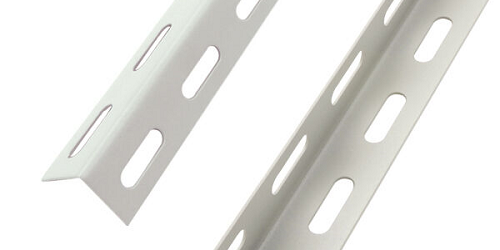
They're typically a meter or two long and have an L-shaped profile. Make a cut in the center of one side of the L and fold the support until it forms a 60-70° angle (see image below). Close the triangle with another piece of profile, and your antenna support is complete. To secure the support to the mast, you can use standard antenna clamps.
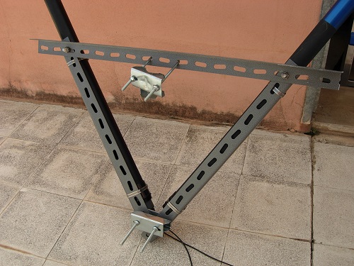
Now we need to attach the rods to the support. Remember to remove the last rod element because it's too thin and fragile, and it doesn't fit through. I used metal ties to secure the rods to the support, but any other method is fine as long as it's secure.
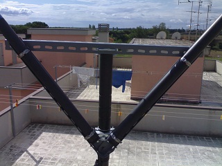
With the rods still closed, insert the radiator's electrical wire into the rods and tie a knot at the base to prevent it from accidentally slipping out. Extend the rods and tension the radiator.
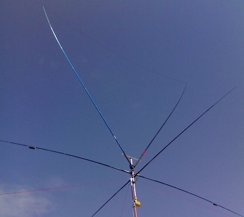
My delta loop in use together with other antennas (10m dipole and crossed with 40m loaded dipole)
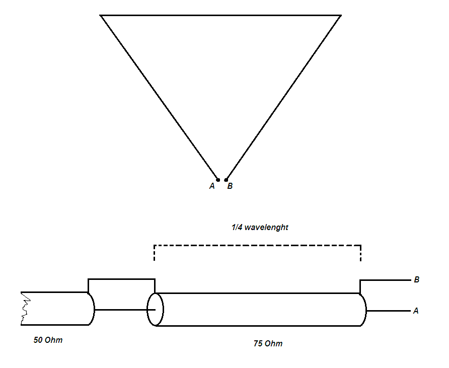
The antenna is physically ready, but we still need to complete one last step: the coaxial cable and the impedance matching line. The impedance of a single loop varies from 120 to 140 Ohms, so it's not possible to power the antenna with the traditional 50 Ohm cable. To match these two different impedances, we'll use a coaxial stub made from 1/4 wavelength of 75 Ohm cable (RG59). To calculate the stub length, we'll use the following formula:
Stub length in meters = ((300/F) /4)*0.66
- 300 is the speed of light propagation;
- F is the frequency in MHz;
- 0.66 is the velocity factor of the RG59 cable.
If you intend to use satellite cable, the velocity factor will vary from 0.85 to 0.88. Refer to the ratings on each cable. If you wrap the stub in coils about 10 cm in diameter, you'll also have created a choke to prevent RF feedback. The next image shows how to connect the power line to the stub.
(((( 📡 IZ0GIF 📡 ))))